Flow Through Fittings
Background and Theory
One of the most common problem in fluid mechanics is the estimation of pressure loss. Calculating pressure losses is necessary for determining the appropriate size pump. Knowledge of the magnitude of frictional losses is of great importance because it determines the power requirements of the pump forcing the fluid through the pipe. For example, in refining and petrochemical industries, these losses have to be calculated accurately to determine where booster pumps have to be placed when pumping crude oil or other fluids in pipes to distances thousands of kilometres away.
Pipe losses in a piping system result from a number of system characteristics, which include among others; pipe friction, changes in direction of flow, obstructions in flow path, and sudden or gradual changes in the cross-section and shape of flow path.
Whenever the velocity of a fluid is changed, either in direction or magnitude, by a change in the direction or size of the conduit, friction additional to the skin friction from flow through the straight pipe is generated. Such friction includes form friction resulting from vortices which develop when the normal streamlines are disturbed and when boundary-layer separation occurs. The form friction is due to the obstructions present in the line of flow, it may be due to a bend or a control valve or anything which changes the course of motion of the flowing fluid.
Fittings and valves also disturb the normal flow lines and cause friction. In short lines with many fittings , the friction loss from the fittings may be greater than that from the straight pipe.
As in straight pipe, velocity increases through valves and fittings at the expense of head loss. This can be expressed by equation similar to Equation 1:
.gif) (1)
(1)Where V is the average velocity of the pipe leading to fitting. Ke is called the resistance coefficient and is defined as the number of velocity heads lost due to the valve or fitting. It is a measure of the following pressure losses in a valve or fitting:
- Pipe friction in the inlet and outlet straight portions of the valve or fitting
- Changes in direction of flow path
- Obstructions in the flow path
- Sudden or gradual changes in the cross-section and shape of the flow path
Pipe friction in the inlet and outlet straight portions of the valve or fitting is very small when compared to the other three. Since friction factor and Reynolds Number are mainly related to pipe friction, Ke can be considered to be independent of both friction factor and Reynolds Number. Therefore, Ke is treated as a constant for any given valve or fitting under all flow conditions, including laminar flow. Indeed, experiments showed1 that for a given valve or fitting type, the tendency is for Ke to vary only with valve or fitting size.
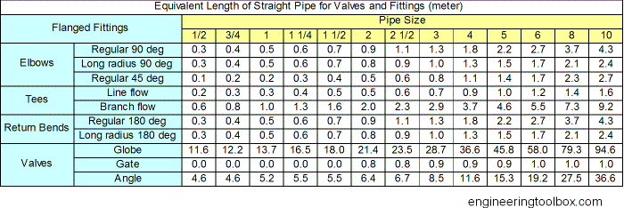
Pressure losses in fittings is usually represented by equivalent length( Leq). It is is the length of a straight pipe that offers same resistance to flow as that offered by the fitting. The ratio L/D is equivalent length in pipe diameters of straight pipe that will cause the same pressure drop or head loss as the valve or fitting under the same flow conditions. The ratio Leq/D is equivalent length in pipe diameters of straight pipe that will cause the same pressure drop or head loss as the valve or fitting under the same flow conditions. Friction loss from different fittings in a pipeline ,must be accounted for when calculating friction losses for each section of pipe. Add the equivalent length of pipe for each fitting or valve that occurs in each section of the pipeline.
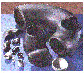
Fittings :
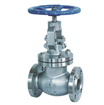
Globe valve :
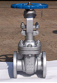
Gate Valve :
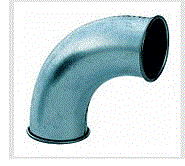
90 degree Bend :
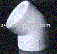
45 degree elbow :
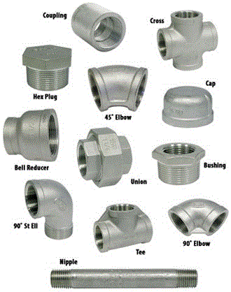
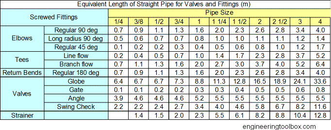
Screwed Fittings - equivalent length in meter :
Equivalent length (in meters) of straight pipe for fittings like bends, returns, tees and valves.
Flanged Fittings - equivalent length in meter :
Equivalent length (in meters) of straight pipe for fittings like bends, returns, tees and valves.
